(space3d)
The @RadiationOutput module stores the 3D position of any electron emitting radiation directly at the detector, effectively creating a three-dimensional map of the origin of the radiation.
Directed radiation, such as bremsstrahlung and synchrotron radiation from relativistic electrons, can only be observed when the emitting electron is moving towards the detector. This is expressed in the equation
where \(\hat{\boldsymbol{b}}\) denotes the magnetic field unit vector, \(\boldsymbol{x}\) is the position of the particle, \(\boldsymbol{X}\) is the detector’s position and \(\theta_{\rm p}\) denotes the particle’s pitch angle at \(\boldsymbol{x}\). The solution to this equation is the so-called surface-of-visibility, which can be studied using the Space3D module.
Summary of options
| Option | Description |
@RadiationOutput(space3d) common |
List of common quantities to include in the output file. |
@RadiationOutput(space3d) output |
Name of output file to generate. |
@RadiationOutput(space3d) pixels |
Number of pixels in each dimension. |
@RadiationOutput(space3d) point0 |
First edge point of pixel box. |
@RadiationOutput(space3d) point1 |
Second edge point of pixel box. |
Specification of pixel box
The Space3D output module creates a 3D histogram of where radiation that reached the detector was emitted from. The histogram is generated in a subset of space that is defined by the pixel box, illustrated below.
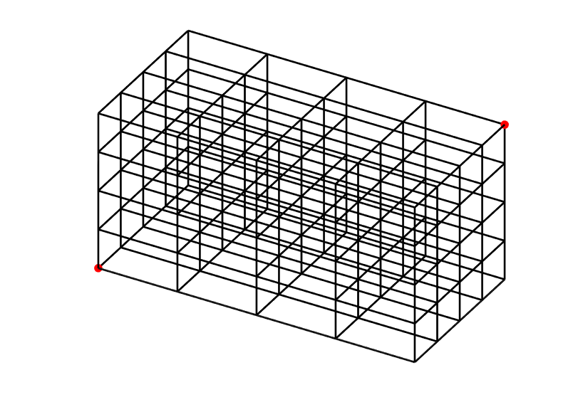
This box is defined by its two edge points, point0 and point1, indicated
as red dots in the figure above, which specify its width, height and depth. The
number of cells, or “pixels”, in the box is the same in each direction, and each
cell records the radiation emitted from its region of space.
Note
One can think of the coordinates of each point as the “minimum” and “maximum”
points respectively of the region to record. Thus, it is a good idea to
always have point0 be element-wise smaller (or larger) than point1,
i.e.
Example configuration
The following example configures a Space3D output module to generate a surface-of-visibility consisting of \(100^3\) cells:
@RadiationOutput ourSpace3D (space3d) {
    output = "ourSpace3D.h5";
    pixels = 100;
    #         X      Y      Z
    point0 =  0.92, -1.06, -0.68;
    point1 =  2.21,  0.60,  0.48;
}
Output file structure
The output file contains the following variables:
| Variable | Description |
image |
Pixel box/resulting image/histogram. |
pixels |
Number of pixels per dimension. |
xmin |
The x-component of point0. |
xmax |
The x-component of point1. |
ymin |
The y-component of point0. |
ymax |
The y-component of point1. |
zmin |
The z-component of point0. |
zmax |
The z-component of point1. |
Common quantities
By default, no common quantities are included with output generated by this
module. To add common quantities, use the
@RadiationOutput(space3d) common option.
All options
-
common¶ Default value: noneAllowed values: See the list on @RadiationOutput. Specifies which “common quantities” to include in the output file. A full list of possible options is given on @RadiationOutput.
-
output¶ Default value: Nothing Allowed values: Any valid file name. Specifies the name of the output file to generate. The file name extension determines the type of the generated file.
-
pixels¶ Default value: Nothing Allowed values: Any positive integer. The number of pixels per dimension in the pixel box.
-
point0
-
point1¶ Default value: Nothing Allowed values: Any vector in 3D space. Coordinates of the two edge points defining the pixel box. By convention, we usually assign the lower limits of each coordinate to
point0and upper limits topoint1.